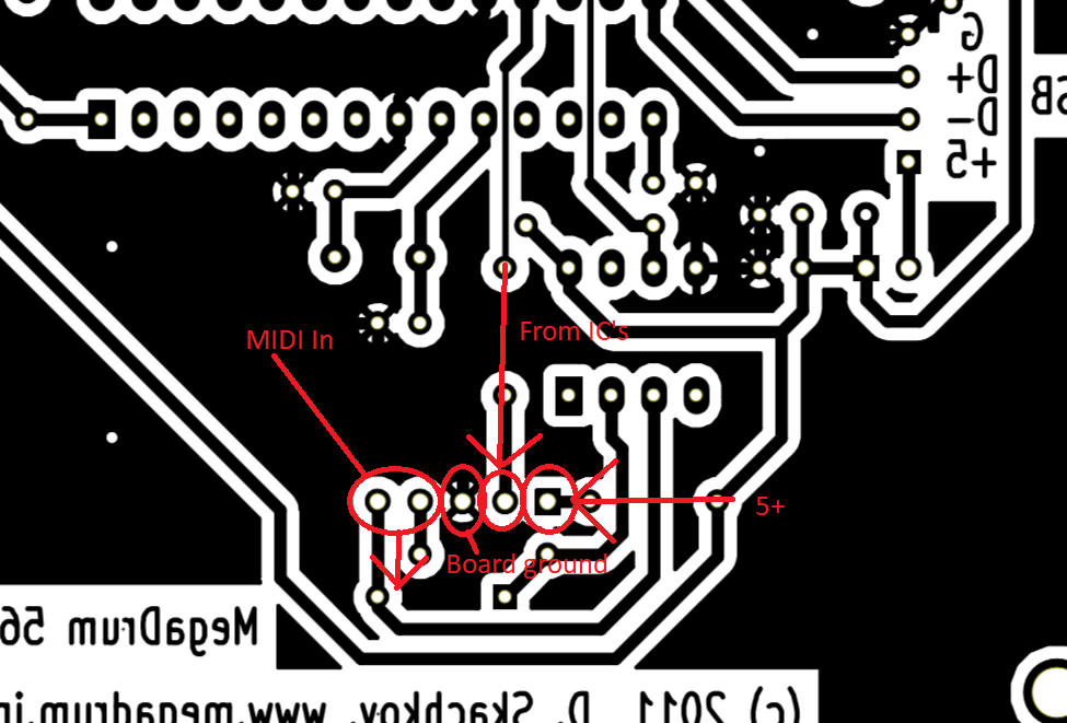
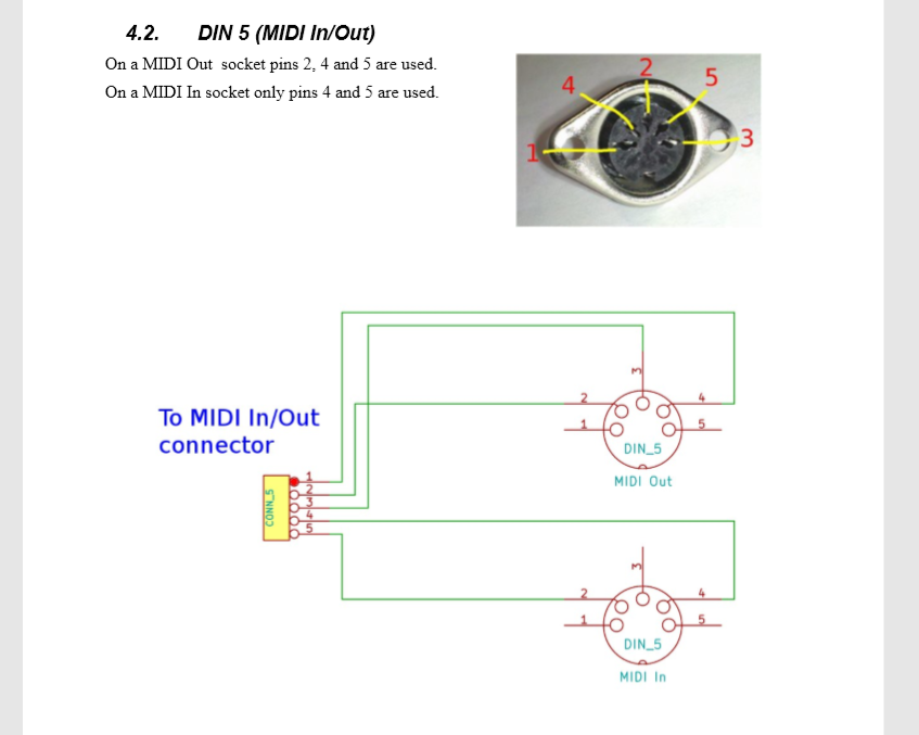
Miswired MIDI port.
So, speaking purely hypothetically you understand, what if some moron happened to mix up the ground and pin 2 of the midi I/O and fire up their freshly built megadrum? (AT644 based)
Said moron Noticed that while these MIDI ports were connected, the LCD screen lit up dimly with the MD main power switch off (jumper), but headscratchingly, only when the USB power cable was attached.
^This really my head as i could find no continuity whatsoever anywhere between the LCD and switch pins. Or indeed the switch pins and anywhere else on the board.
But then I realised it only happened with the MIDI ports connected.
Then I noticed the ground wire mixup.
So from this I infer that power must have been coming from the MIDI-USB cable I had connected and grounding through the USB?
Turns out pins 1 and 2 were also reversed after i fixed the ground problem, so that may have done some damage too (was looking at the schematic like it was the back of the port like a tit).
With this in mind, what damage has said moron likely done to his board?
The midi is definitely not working as expected at the moment.
With the MIDI ports correctly wired, I get no sysex or led activity at all (firmware updater just CRC errors too).
If I connect the MIDI pins backwards on the board (to I and O reversed). I do get sysex and led flashes, but the megadrum drops out of bootloader mode almost the moment I start the update. (which makes some sense to me as there would now be no ground on what it thinks is the midi out)
I have also noticed scrambled characters on the LCD when this happened, but i was moving the board at the time so might just have been dodgy LCD connections.
To be clear, I am indeed the moron in question
I have spares for every component and have been using the PCB from page 2 of this thread https://www.megadrum.info/forums/viewtopic.php?f=3&t=3882&start=10
I'm also still waiting for a PICkit to arrive so I can program the USB firmware, so I can't test anything over that for a couple of days, but will report back when I can.
I already have a couple of ideas but any guidance about which IC pins and components I should pay special attention to would be greatly appreciated.
Regards all.

